

Calibration
Calibrate BeamTracker to accurately classify machine runtime and downtime based on part flow, ensuring meaningful utilization and OEE reporting.
Overview
BeamTracker determines machine runtime based on the time between parts passing through the sensor beam. Because every production line operates at different speeds, calibration helps ensure that the system correctly identifies when the line is running versus stopped.
Proper calibration ensures accurate utilization, OEE, and downtime reporting.
Why calibrate?
- Ensure accurate part counting
- Properly classify running vs. stopped states
- Reduce false downt ime alerts
- Optimize utilization reporting
When to calibrate:
- After initial installation (required)
- When production line speed changes
- If part counts seem inaccurate
- After moving the device to a new location
Estimated time: 10-15 minutes
Prerequisites
Before starting calibration, ensure:
- BeamTracker is installed and powered on
- Device is connected to the internet (showing on BeamTracker screen)
- You have access to the IoTFlows Dashboard
- Production line is operational
- You can observe parts flowing through the detection zone
Calibration Process Overview
Calibration is a two-part process:
Part 1: On-Device Sensor Calibration
Sets the physical detection range of the laser sensor.
Part 2: Web Dashboard Calibration
Fine-tunes how the system interprets sensor data to classify runtime and downtime.
Part 1: On-Device Sensor Calibration
This initial step configures the BeamTracker's physical sensing limits, ensuring it only detects relevant objects.
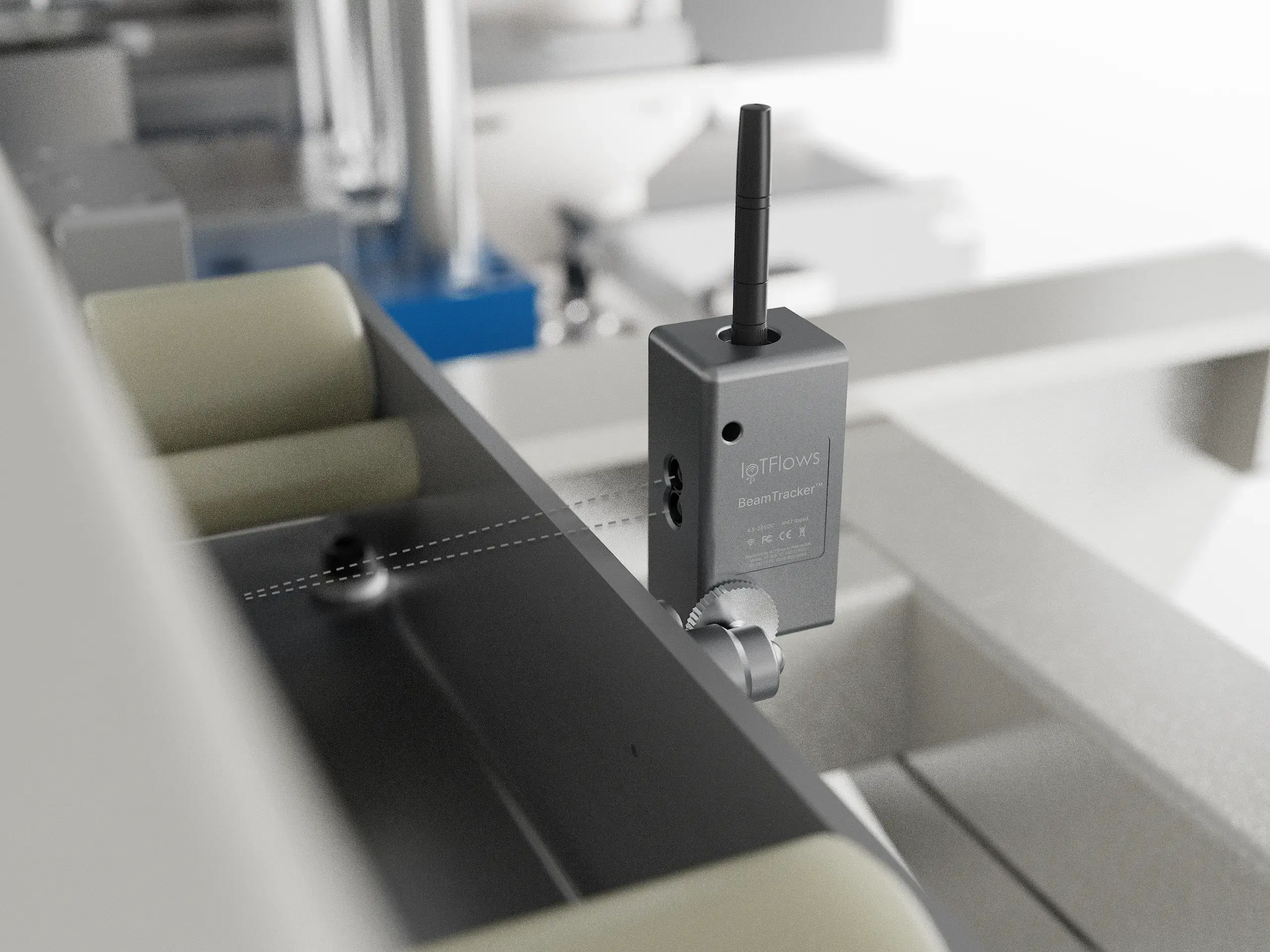
Step 1: Mount the Sensor
Position the BeamTracker so its invisible laser beam crosses the path of the objects you want to count. For best results, ensure a clear, stable line of sight to the detection area.
Step 2: Access Calibrate Sensor Page
On the BeamTracker's built-in screen:
- Tap the Settings icon (top right corner)
- Navigate to the Calibrate Sensor page
Step 3: Set Maximum Detection Range
- The screen will display the current distance the sensor is reading
- Ensure no objects are in the beam's path, so it's reading the distance to the background surface
- To set a maximum detection range and ignore anything farther away:
- Temporarily place an object at your desired maximum distance
- The sensor will lock onto this distance
- Press the Calibrate button
Result: Once calibrated, the sensor will only register objects that are closer than the set distance, ignoring the background and any movements beyond it.
Part 2: Web Dashboard Calibration
After setting the physical sensor range, configure how the IoTFlows platform interprets the data for accurate production monitoring.
Step 1: Access the Calibration Page
- Open the IoTFlows Dashboard
- Select the machine associated with the BeamTracker device
- Click the BeamTracker device to open the configuration panel
- Navigate to the Calibration tab
![]()
Step 2: Understanding Calibration Parameters
The Calibration tab includes two key parameters that work together:
- Downtime Filter
- Auto-Classify Downtimes
These settings determine how part flow translates into Running and Stopped states, and how stoppages are categorized.
![]()
Step 3: Configure Downtime Filter
The Downtime Filter specifies how long the machine is considered running after the last part is detected.
How it works:
- Each time a part passes in front of the sensor, the timer resets
- If no new part passes within the set time, the machine is marked as stopped
- The stop time is back-dated to the actual time the last part passed
| Event | Result |
|---|---|
| Parts continue passing within the filter duration | Machine stays running |
| No part passes longer than the filter duration | Machine switches to stopped (back-dated to last part) |
Recommended Filter Values:
| Production Pattern | Recommended Filter |
|---|---|
| Fast continuous production | 15–45 seconds |
| Moderate paced operations | 1–5 minutes |
| Batch or intermittent work | 5–20 minutes |

Step 4: Configure Auto-Classify Downtimes
Once the machine is considered stopped (based on the Downtime Filter), the Auto-Classify Downtimes parameter determines whether a stoppage is automatically labeled as a "Short Downtime."
Example Configuration:
| Parameter | Value |
|---|---|
| Downtime Filter | 10 minutes |
| Auto-Classify Downtimes | 30 minutes |
Results:
- Stoppages shorter than 10 minutes → Ignored (machine treated as still running)
- Stoppages between 10 and 30 minutes → Automatically labeled as "Short Downtime"
- Stoppages longer than 30 minutes → Require manual classification or follow standard downtime workflows

Assets Overview → Adjust Status Colors When to use Auto-Classify:
- You want to track all downtimes but automatically handle quick pauses
- Reduce operator workload for classifying brief stoppages
- Distinguish between minor pauses and significant downtime events
Calibration Summary
| Parameter | Purpose | Effect |
|---|---|---|
| Downtime Filter | Defines how long the machine remains running after the last part | Prevents rapid switching between running and stopped |
| Auto-Classify Downtimes | Assigns short stoppages to an automation category | Reduces operator workload for quick pauses |
Calibration Validation
After completing calibration, validate that your settings are working correctly:
1. Test with Actual Production
- Run your production line normally
- Watch parts flow through the BeamTracker's detection zone
- Verify part counts on the dashboard match actual parts
2. Review Recent Data
- Check the last hour of data on your dashboard
- Verify running/stopped states match actual line operation
- Look for any unexpected downtime classifications
3. Monitor Over Time
- Observe performance over the next 24-48 hours
- Look for patterns of mis-detection
- Adjust Downtime Filter if you see too many short stops or too few
Common Calibration Mistakes
❌ Setting Downtime Filter too short → Creates excessive stop/start cycling, inflating downtime counts
❌ Setting Downtime Filter too long → Misses real downtime events, shows artificially high utilization
❌ Sensor range not calibrated → Detects background movements or misses actual parts
❌ Not testing with actual production → Settings may not match real-world part flow patterns
✅ Best Practice: Start with recommended values for your production pattern, then fine-tune based on actual observed behavior over 24-48 hours.
Troubleshooting Calibration Issues
Part Counts Don't Match Actual Parts
Problem: BeamTracker shows different count than actual parts produced
Solutions:
- Re-calibrate the sensor range on the device
- Ensure laser beam is perpendicular to part flow
- Check for reflective surfaces causing false detections
- Verify parts are passing through the detection zone consistently
- Ensure no background movements are being detected
Too Many Short Downtimes
Problem: Dashboard shows many brief stops that don't reflect real downtime
Solutions:
- Increase the Downtime Filter value
- Parts may be spaced farther apart than filter allows
- Consider your line's normal part-to-part timing
Utilization Appears Too Low
Problem: Dashboard shows low utilization despite line running normally
Solutions:
- Increase the Downtime Filter — may be marking normal gaps as downtime
- Review Auto-Classify settings — may need to increase threshold
- Check if parts-per-minute matches expectations
Utilization Appears Too High
Problem: Dashboard shows high utilization but line has significant downtime
Solutions:
- Decrease the Downtime Filter — may be missing actual stops
- Ensure sensor is detecting all parts correctly
- Verify BeamTracker is positioned correctly
Best Practices
For Fast Production Lines (< 1 second between parts):
- Use shorter Downtime Filter (15-45 seconds)
- Monitor closely for false positives
- Ensure stable mounting to prevent vibration-induced miscounts
For Moderate Production (1-10 seconds between parts):
- Use medium Downtime Filter (1-5 minutes)
- Balance between responsiveness and stability
- Typical for most packaging and assembly lines
For Batch Production (variable timing):
- Use longer Downtime Filter (5-20 minutes)
- Higher Auto-Classify threshold
- Manually review downtime classifications regularly
For Multi-Lane Lines:
- Contact support for multi-device configuration
- Each lane may need separate BeamTracker
- Coordinate Downtime Filters across lanes
Summary
- ✅ Calibration is a two-part process: on-device sensor + web dashboard
- ✅ Downtime Filter controls when line switches from running to stopped
- ✅ Auto-Classify Downtimes automates categorization of short stops
- ✅ Calibration should match your production line's specific characteristics
- ✅ Always validate calibration with actual production data
- ✅ Fine-tune settings based on observed performance over 24-48 hours
Next Steps
After successful calibration:
- Monitor part counts over the next production run
- Compare dashboard data to actual production records
- Set up alerts for slow production or unexpected downtime
- Fine-tune parameters if needed based on actual behavior
Continue learning:
Ready to optimize your production line monitoring? Remember: calibration is an ongoing process — adjust as your production patterns evolve!