

Installation
Step-by-step guide to physically installing and powering up your BeamTracker device for production line monitoring.
Overview
This guide walks you through the physical installation of your BeamTracker device.
What you'll do:
- Unbox and inspect components
- Connect the antenna
- Choose optimal mounting location
- Mount the device with bracket/fixture
- Connect power and verify first boot
1. Unboxing & Inspection
When your BeamTracker arrives, verify all components are included and in good condition.
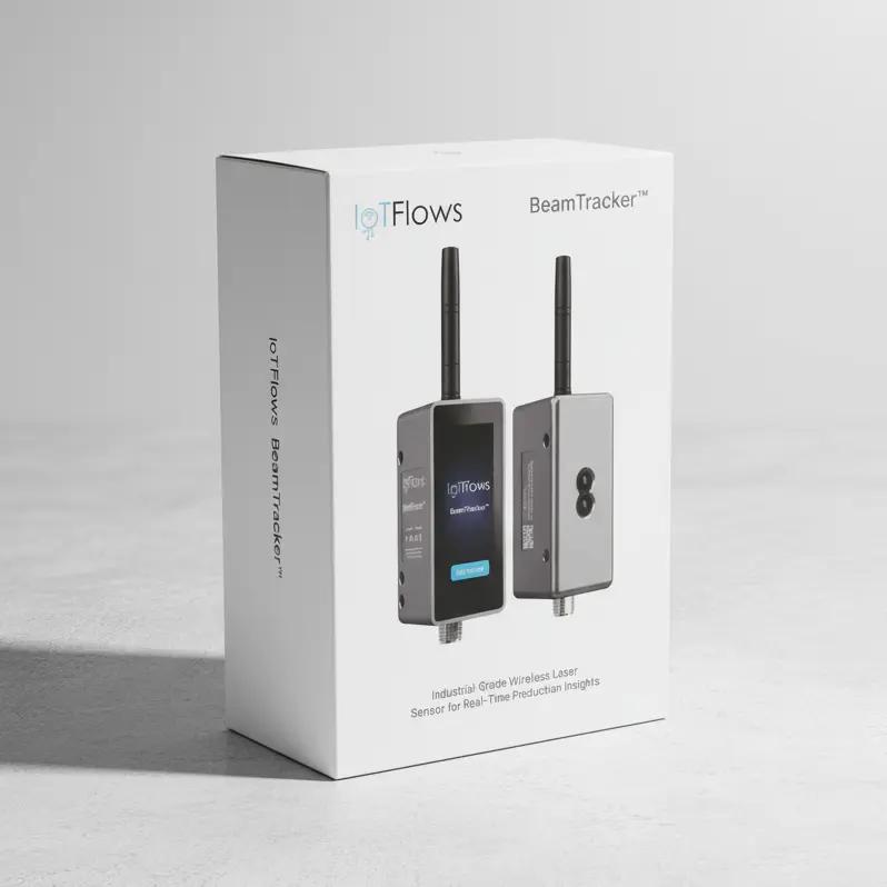
Included in the box:
- 1× BeamTracker device with built-in touchscreen
- 1× External antenna
- 1× M12 Power adapter OR 1× M12 power cable + 1× M12 T-Splitter (Sold Separately)
- 1× Mounting bracket or fixture (Sold Separately)
2. Physical Installation
Step 1: Connect the Antenna
Before mounting, attach the external antenna to the BeamTracker device:
- Locate the antenna connector on the device
- Align and thread the antenna connector
- Hand-tighten until secure (do not over-tighten)
- Ensure connection is snug but not forced
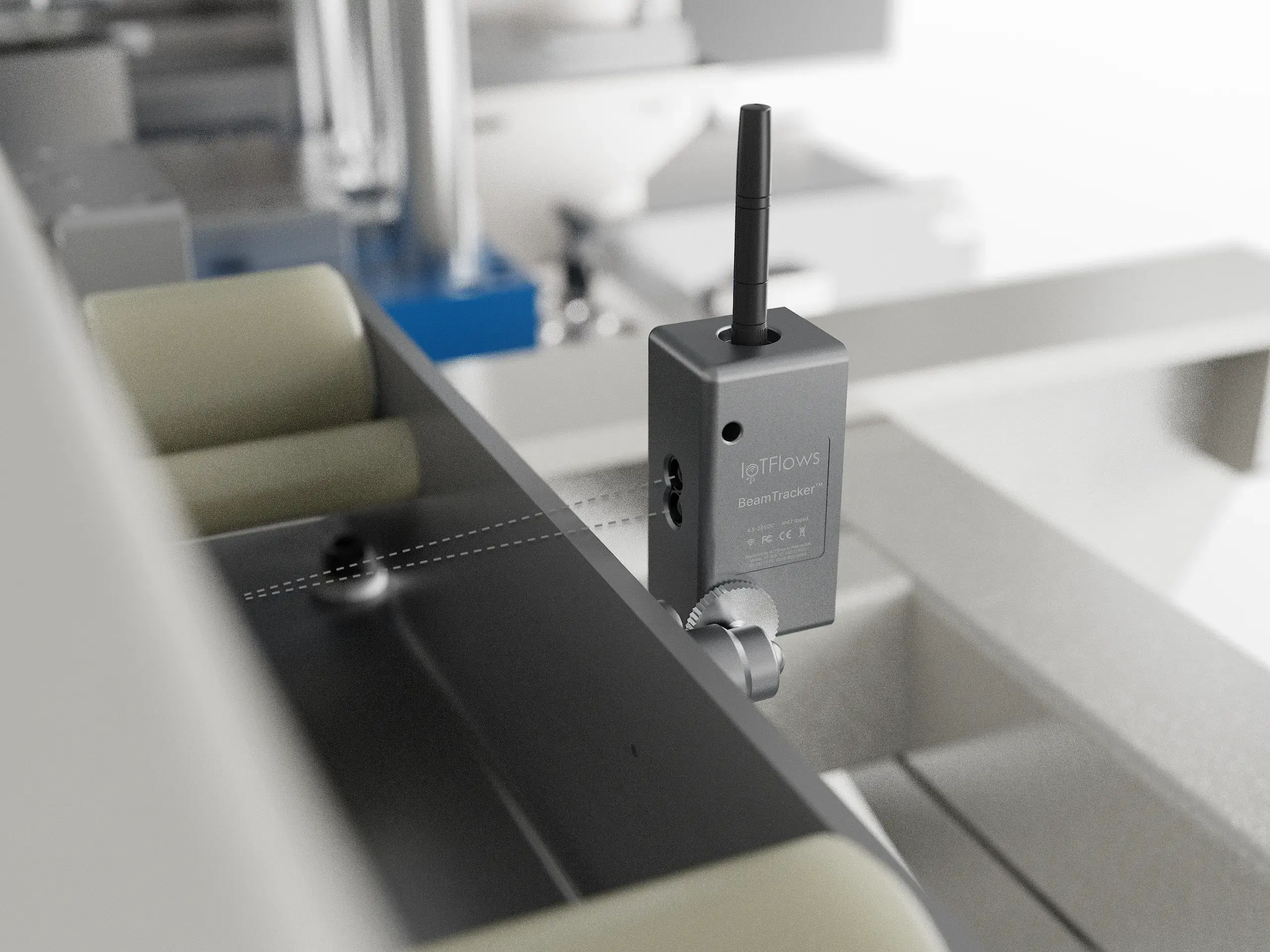
Step 2: Choose a Mounting Location
Select a mounting location that provides optimal laser detection:
For accurate part counting:
- Clear line of sight across the part flow path
- Stable positioning perpendicular to motion path
- Appropriate distance from parts (typically 0.5-3 meters, adjustable during calibration)
- Consistent detection zone where all parts pass
Step 3: Understanding Laser Detection
BeamTracker uses a single-point, invisible laser for detection, not a camera or wide-angle LiDAR.
Think of it as a precision tripwire:
- Single laser point detects objects passing through
- Invisible laser (safe for operators and products)
- Non-contact measurement (no interference with production)
- Detects objects within calibrated distance range
Detection requirements:
- Part must pass through the laser beam
- Part must be larger than the laser point
- Part must interrupt the beam clearly (not transparent)
- Background surface should be stable (not moving)
Step 4: Mount the Device
Using the provided mounting bracket or fixture:
-
Secure the bracket to your chosen mounting surface:
- Use appropriate fasteners for surface material
- Ensure bracket is level and stable
- Verify bracket won't vibrate during production
-
Attach BeamTracker to bracket:
- Follow bracket-specific mounting instructions
- Ensure device is firmly attached
- Orient screen for easy viewing
-
Align the laser beam:
- Position device perpendicular to part flow
- Aim laser to cross part path at consistent point
- Ensure beam will detect each passing object
-
Verify positioning:
- Check laser path is clear
- Ensure parts will pass through detection zone
- Verify no background movements in detection area
- Test that screen is visible from operator position
3. Powering Up Your Device
Connect Power
BeamTracker uses industrial M12 connectors for reliable power delivery:
-
Connect M12 cable to device:
- Align the keyed connector
- Push firmly until it clicks
- Hand-tighten the locking collar
-
Connect to a power source or T-Splitter:
- M12 Power adapter: Plug the adapter into a standard AC outlet (100–240 V AC), or
- M12 T-Splitter: Connect the other end of the M12 cable to a T-Splitter to enable shared, daisy-chained power


First Boot Sequence
After powering on, observe the built-in screen:
- Screen lights up and displays startup sequence
- Device performs initial checks
- Boot screen appears with IoTFlows branding
- One of two things will happen:
- If you ordered a 4G/LTE router: Device automatically connects
- If connecting to WiFi: Screen shows WiFi setup instructions with QR code
Startup screens:


Troubleshooting Installation Issues
No Screen Display / Device Won't Power On
Symptoms:
- Screen is completely dark
- No response when powered
- Device appears dead
Solutions:
-
Check M12 connections:
- Verify M12 cable is fully seated and locked on both ends
- Check for bent pins or debris in connectors
- Try disconnecting and reconnecting
-
Check power source:
- Verify outlet has power
- Try different outlet
- If using industrial power, verify voltage (12-24V DC)
- Test power adapter with multimeter if available
-
Check device:
- Look for physical damage to enclosure or screen
- Verify antenna is connected
- Contact support if device still won't power on
Screen Dim or Hard to Read
Problem: Screen displays but is difficult to see
Solutions:
- Adjust screen brightness in device settings menu
- Reduce glare — reposition device or add shade
- Check ambient lighting — very bright environments may require repositioning
- Clean screen — remove dust or smudges with soft, dry cloth
Laser Not Detecting Parts
Problem: Parts pass through detection zone but aren't counted
Solutions:
-
Verify laser is enabled (check device screen)
-
Check alignment:
- Ensure laser crosses part path
- Parts must physically interrupt the laser beam
- Background surface should be stable
-
Recalibrate sensor range (covered in calibration guide)
-
Check for transparent parts — very clear materials may not interrupt laser
-
Verify mounting stability — vibration can cause misalignment
For detailed troubleshooting, see the Troubleshooting Guide.
Bracket/Mounting Issues
Problem: Difficult to mount or bracket doesn't fit
Solutions:
- Verify bracket type matches your application
- Check mounting surface is appropriate for fasteners
- Contact support for alternative mounting solutions
- Consider custom bracket for unusual installations
Installation Checklist
Before proceeding to network setup, verify:
- ✅ Device is securely mounted and stable
- ✅ Laser beam crosses part flow path at consistent point
- ✅ Antenna is connected and has clearance
- ✅ M12 power connections are secure and locked
- ✅ Device powers on (screen displays startup sequence)
- ✅ Screen is accessible for interaction
- ✅ Device doesn't interfere with production operation or safety
- ✅ Mounting location allows clear part detection
Next Steps
✅ Installation complete!
Now proceed to network setup:
→ Continue to Network Setup to connect your device to the internet.
Need help?