

Install and align BeamTracker
Mount a BeamTracker across the part flow, aim the beam, and confirm it booted.
BeamTracker counts units as they pass a point. It fires an invisible laser across the path parts travel, and each part that breaks the beam registers a count. Where you aim it decides what gets counted, so mounting and aiming are the whole job.
This page ends with a powered, aimed device. Setting the detection thresholds is a separate procedure, in Calibrate BeamTracker.
Before you start: have the line stopped and safe to reach into, and have the mounting bracket and M12 power on hand. Both are ordered separately from the device.
Check what is in the box
The box holds the device, with its built-in touchscreen, and one external antenna. The mounting bracket, the M12 power adapter, and the M12 cable are ordered separately.
Inspect before you mount. Check the screen and enclosure for damage, the M12 connector for bent pins, and the two lenses on the front face for fingerprints or shipping film. A smeared lens is a weak beam.
If a part is missing or damaged, stop and contact support.
Connect the antenna
Thread the external antenna onto the connector and hand-tighten it. Use no tools, and stop when it is snug.
Connect it before powering the device on, because without it the radio has almost no range and the device will not hold a connection.
Understand how the beam works
A tripwire is the right mental model: BeamTracker fires one invisible laser point from the front face and watches for that point to be interrupted. It is not a camera and not a wide-angle scanner, so it sees only what crosses that single line.
The device is one unit. There is no reflector to mount opposite it, and nothing to align it against beyond the surface the beam lands on.
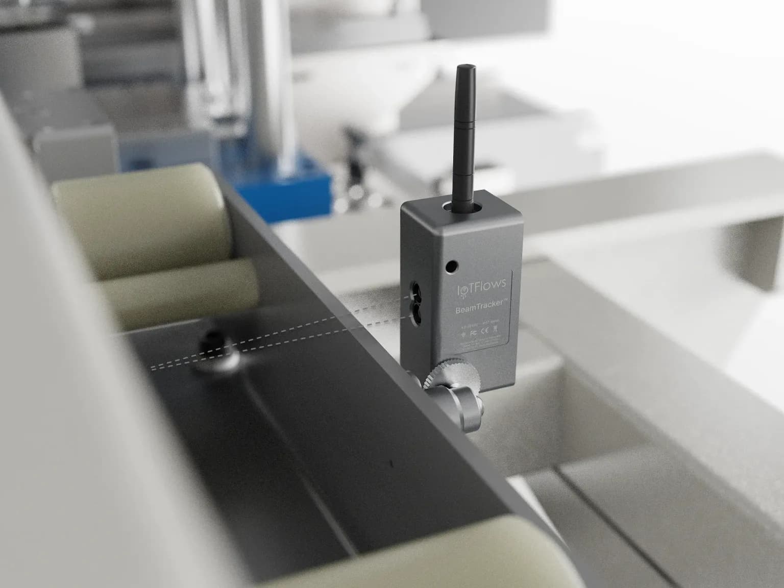 BeamTracker fires a single beam across the part path from the lens pair on its front face. One unit, no reflector: the beam simply lands on whatever is opposite.
A part is counted when it interrupts that beam, which means it has to be bigger than the laser point, opaque enough to block it, and travelling through the line rather than past it. Glass and clear film may not register at all.
The background matters too. Aim across a stable surface, because anything moving behind the part path can break the beam on its own and add counts nobody made.
Choose a mounting point
Aim for a point where every good part passes the beam and nothing else does. That single sentence decides most installations.
A beam that also catches an operator's hand will count hands. A beam across a spot where parts are stacked, reworked, or set down will count each pass. Pick the narrowest point in the flow where finished parts move one way and nothing else crosses.
The location also has to give you:
- A clear line of sight across the part path, perpendicular to the direction of travel.
- A working distance of up to 8 meters (26 ft) from the device to the part path. The beam resolves to the millimetre across that range, and the cutoff beyond which it ignores everything is set during calibration.
- A stable background behind the part path, with nothing moving in it.
- A readable screen. Setup and status live on the device, so an operator has to be able to see it.
Coolant, cutting fluid and wash-down are not constraints. BeamTracker is IP67, so pick the point that gives the beam a clean run rather than retreating to a dry spot. What the beam cannot survive is a path it cannot see across: mist, airborne chips and spray break a reading in a way the housing does not.
 BeamTracker on its L-bracket: the screen faces the operator, the antenna clears the top, and the M12 cable leaves the bottom. The two bolts in the slotted arc are what you loosen to aim the beam.
Mount and aim the device
- Fasten the bracket to the surface you picked, using fasteners suited to that material. Check it is level and that it does not move when the machine runs.
- Attach the BeamTracker to the bracket and tighten it down, with the screen turned toward where an operator will stand.
- Aim the front face square across the part path, so the beam crosses at one consistent point.
- Run a part through and watch that it breaks the beam cleanly.
A bracket that vibrates walks the beam off its target over a shift, so the tug test at step 1 matters more here than on a magnet-mounted sensor.
 A BeamTracker counting a bottling line: each bottle crossing the beam adds one to the count on the device screen, which reads Running while parts keep arriving.
Connect power
BeamTracker takes 4.5 to 28 V DC over M12. The rating is printed on the device label, which is the authority if a document disagrees.
Connect the M12 cable to the device first: align the keyed connector, push until it clicks, then hand-tighten the locking collar. An M12 joint resists vibration only when it is fully seated and locked.
Then power the other end with either the M12 power adapter, into a standard 100 to 240 V AC outlet, or an M12 T-splitter, to daisy-chain from power already running to a nearby device. Choose the splitter when several devices sit close together and you do not want an outlet for each.
Confirm first boot
The screen lights as soon as the device has power, runs its startup checks, and shows the IoTFlows boot screen. What happens next depends on how this device reaches the internet.
- On an IoTFlows 4G/LTE router: the device connects on its own. See Connect a device through the 4G/LTE router.
- On facility Wi-Fi: the screen shows setup instructions and a QR code. Provision it from the mobile app, in Connect a device to Wi-Fi.
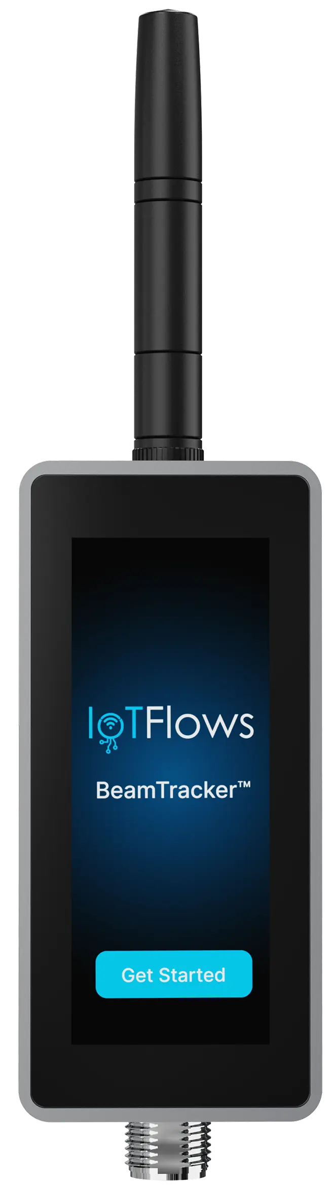
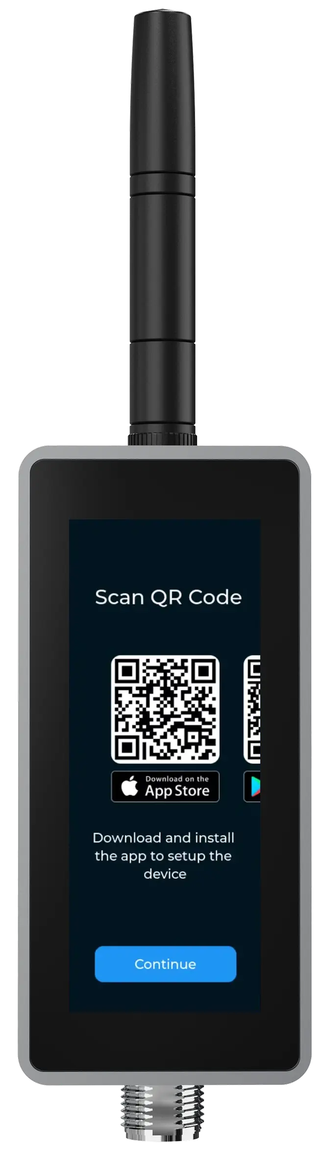
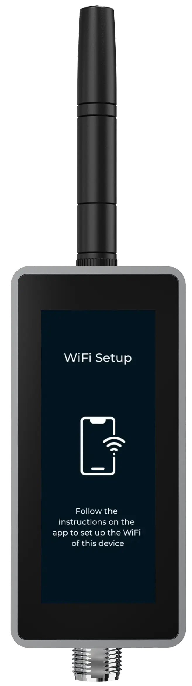
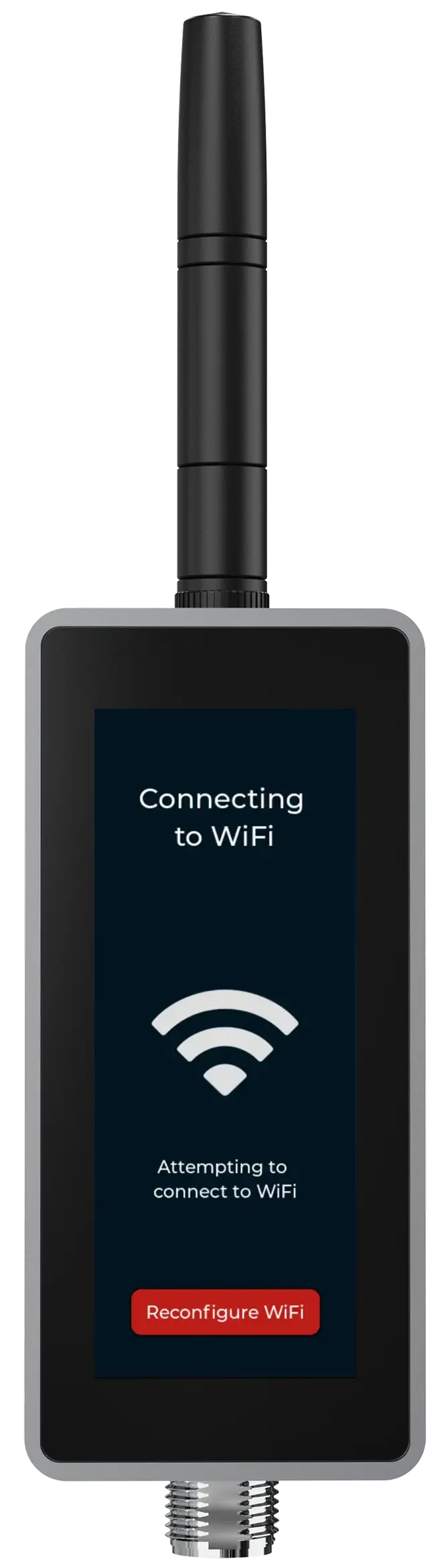 The startup sequence on the device's own screen, in order: the get-started screen, the QR code that opens the mobile app, Wi-Fi configuration mode, and the device connecting.
The screen is touch-enabled, and it is where the device reports a beam that is not landing where it should. If it says the beam is misaligned, re-aim the front face before going further, then set the detection range in Calibrate BeamTracker.
If the screen stays dark
- Reseat the M12 cable at the device end and lock the collar.
- Reseat the other end at the adapter or the T-splitter.
- Look into both connectors for bent pins or packed debris.
- Confirm the outlet is live, or that an industrial supply sits within 4.5 to 28 V DC.
If the screen stays dark on a known-good supply, contact support with the device serial from the label. For a device that powers up but will not stay online, see Troubleshoot a device that is offline.
See also
Mount a SenseAi Embedded on the motor or spindle it should read, connect the antenna, power it over M12 at 4.5 to 28 V DC from either the supplied adapter or a T-splitter, and confirm first boot; the sealed IP67 housing is what lets the unit sit in coolant and wash-down close to the source, and the job takes 5 to 45 minutes depending on how reachable that spot is.
Put any IoTFlows sensor onto a 2.4 GHz network using Bluetooth from the mobile app: hold the Wi-Fi button until the LED blinks blue, or open WiFi Configuration on the BeamTracker touchscreen, then hand the device its credentials from the phone and save the network to your organization so the next device provisions without retyping it.